|
INTERNAL SPINNAKER HALYARD AND POLE CONTROLS (Updated 7 Jan 07. This was originally
written when the old, gold-anodized Proctor mast was the only Wayfarer
mast, and is aimed at conversion of the set-up found on these masts.) Rationale:
This is a major operation, requiring two people and the better part of
a day's work. If you are at all serious about using your spinnaker, it
is however, well worth that one day of effort to get years of trouble
free
work from these systems. Ours have now been in constant and hard use
over
4 seasons and nothing has ever fouled up or needed repair. (Uncle Al’s
note: This was written in 1981. Since then, we’ve replaced the various
parts of the system only twice! And everything was still working when
the mast finally broke at the 2005 Midwinters!) Even when something does go,
the repairs
will be relatively simple since all the hard work needs doing only the
first time.
Note: In the early 90's, our mast began
to crack at block #4, just above deck level on the front of the mast.
This was likely caused by the fact that I did not know to round off all
the corners inside the cut-out made to accommodate block #4. I have
since learned to do the required rounding, and also to add a mast
sleeve to help strengthen the mast at this potentially great stress
point. When I discovered the crack, I (messily) covered the (w)hole
area with carbon fibre and then added an aluminum sleeve (available
from Proctor/Selden Masts) that stuck out about an inch or two above
deck level. I subsequently moved block #4 about 6" above the foot of
the mast, still on the front of the mast. This required my lengthening
the downhaul rope from 7 to 10 feet, and drilling a hole through the
deck directly in front of the mast and as close to it as possible - the
further from the mast this hole is, the greater the tendency of the
pole to want to swing towards the forestay. I protected the hole in the
deck with a Thru-Deck Bushing such as R3044 shown at the Annapolis
Performance Sailing site at http://www.apsltd.com/Tree/d3000/e534.asp.
Based on my experience, I would recommend keeping block #4 below decks,
just to be on the safe side!! Gear required:
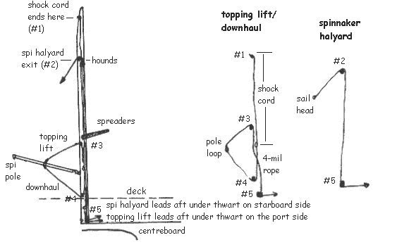
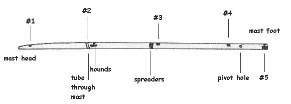
We will be putting five new holes into the mast: four in front and one in the aft face. See diagram below:
Hole 1: Drill a 1/4" hole into the front of the mast just below the uppermost black band. Use a round file to enlarge slightly and to remove all sharp edges to lengthen the life of the shock cord that will emerge from this hole. Hole
2: (Older Proctor masts only – thank goodness!) This is the
toughest one. Using a ½” bit, drill out the tube that runs
through
the main body of the mast just above the hounds. Enlarge this hole into
a vertical rectangle 14x52mm by further drilling and liberal use of the
flat file. Be sure that the
rectangle
is not so close to the forestay fitting that the lower lip of the
halyard
block (HA6) which will go into this spot ends up on the forestay
fitting.
Also remember that a rectangle that is too small can be made larger but
once your hole is too large it cannot be shrunk and the mast will be
needlessly
weaker!
The two RF 453 blocks (Ronstan) to be used for the pole controls require 8 x 25 mm vertical rectangles which I started off by drilling two ¼” holes one at each end of the rectangle. Complete the rectangular cut-out with a jib saw after which the sides can be filed straight. You will need to file slight indentations halfway down both sides (round file) to allow the block axle to enter the mast. The final touch needed will be to use the round file to file a 1/4” diameter semi-circle (removing all sharp edges) at the top of rectangle 3 and at the bottom of rectangle 4 (where the rope will emerge). Before making these holes, check to see if rivet holes already exist in the vicinity and be willing to move the hole up or down an inch or two to incorporate the existing hole(s) into your rectangle. Hole
5: Now we go to the very bottom of the mast where the double
block (HA7) will go into the aft face of the mast. You will need to
remove
the bottom four inches of mast groove to lay bare the flat aft face of
the mast. I did this as follows: Step B: Insertion of shock cord, ropes and blocks It helps to have
two people
to thread shock cord and ropes into the mast. After some horrible
experiments
with whipping thread and sinkers, I discovered the electrician’s “fish
tape” which does a great job. What I found useful was to more or less
permanently
attach (with clove hitches covered by duct tape) about a foot of
whipping
thread to the end of the fish tape. I put a bowline into the loose end
and then tie an appropriate length of whipping thread onto that with
another
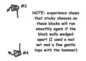
bowline. 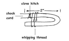 Double the cord as shown above. Hold the loop tightly together and wind about 15-20 turns of whipping line as tightly as you can around the base of the loop like a whipping. Finish with a tight clove hitch around each side of the loop. You may want to then wind another 15-20 turns in the other direction before finishing off with yet another clove hitch. This is probably overkill but I want this to last for 20+ years without having to go back into the mast for repairs. Finally, I knot the two loose ends of whipping line together and burn the ends so that they (gently) melt into the knot. Overkill, as I mentioned! 4. Once the loop is secure, the seven (ten??) foot length of downhaul is tied into the loop with a bowline (the only safe knot!!) 5. We then thread one RF 453 block onto the downhaul and keep it from falling off with a figure eight knot in the loose end. 6. The loop-bowline connection is now gently nursed into hole #4, and then the entry block can be riveted into place. Rivet notes: Set blocks in without riveting first, in order to confirm that ropes can run smoothly without chafing. These blocks are somewhat touchy as the walls tend to buckle a wee bit under pressure when the rivets go in. This causes the sheave to become reluctant to turn. To avoid this, drill slightly oversize rivet holes in mast. I find that I can't drill all four rivet holes at once and then still have them all in the right place for rivets 2, 3 and 4. So my routine has become drill 1 - rivet 1, drill 2 (diagonally across from 1), rivet 2, drill 3, rivet 3, etc. (I have also found that riveting only two of the four holes - either of the diagonal pairs - will do the job adequately since there is little stress on these beyond their task of keeping the entry blocks from falling out of the mast.) If riveting does squeeze the walls of my blocks together and prevents the sheave from turning freely, I remedy this problem by wedging a nail set in between the sheave and the block wall as though I were threading a line into the block, and gentling tapping the nail set with a hammer. This does not take much doing but is important! After all, it is (obviously??) essential to the smooth and breakdown-free operation of your system that all block sheaves must turn with a minimum of friction! The downhaul should be tied around the body of the mast with a clove hitch with a bit of pressure on the cord (to keep it from getting tangled up in the ensuing threading operations). 7. The "fish tape procedure" is now repeated into hole #3, such that the whipping line eventually emerges from hole #5. This time, the whipping line will be clove hitched to the 20' of 4-mil rope that will become the topping lift (= pole uphaul). 8. Use the whipping line to pull the 20' topping lift into into the mast such that its ends hang out of holes #3 and #5. 9. Thread the other RF 453 block onto the free end that hangs out of hole #3 before riveting the RF 453 entry block into its hole #3 position. Secure both ends of the topping lift rope around the mast with clove hitches in order to take up any unreasonable slack inside the mast (snag prevention!!!). As you start your clove hitch near hole #5, pull to the port side of the mast where the uphaul will exit. 10. The fish tape-whipping line combo then makes a third and final appearance to thread the spinnaker halyard from hole #2 to hole #5. The top end of the 45' spinnaker halyard is threaded through the spinnaker halyard block (HA6) once the rope is properly in the mast. HA6 is then riveted into place. Put a figure 8 stopper knot in the halyard end that exits the HA6 block. 11. Double exit block HA7 now goes into hole #5. Thread a good ten feet of spi halyard through the starboard side of the block. Then untie the topping lift clove hitch from the foot of the mast and thread it through the port side of block. Insert block HA7 into its hole, being sure not to twist the ropes. Use the four screws provided (or rivets for the upper pair of holes) to fasten HA7 to the aft face of the foot of the mast. Step C: Adjustments to Topping Lift and Spinnaker Halyard (Cleats, etc) 1.
Topping Lift/Downhaul: Using bowlines, attach topping lift
(coming
from hole #3) and downhaul (from hole #4) (likely up through the deck) to
your pole attachment mechanism
(hook, loop on pole, etc.). Once the mast is back in your boat, set
your
pole and pull it up to its maximum desired upward angle (usually about
20º above horizontal) and hold it there. The downhaul is
deliberately somewhat too
long to allow for personal preferences. Untie it and feed its loose end
through the eye in the hook or the lower part of your pole loop while
the
pole is set at maximum upward angle. Pull loose end until no more
downhaul
will come out and mark the spot where the downhaul rope hits the hook
eye
or pole loop. Then stow the pole and make a bowline in the downhaul to
attach it to the hook eye or pole loop with the mark in its correct
position.
This keeps the pole from skying to higher than desired angles. Once you
are sure it won't be needed, you can remove the excess rope.
Note: the old system with the #4 hole
was really great since the mast could be taken down for travel without
untying the downhaul. When it comes up through the deck, that is, alas,
no longer an option!  |